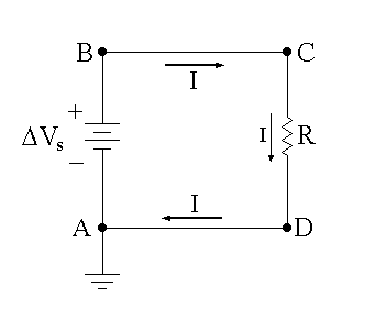
The circuit diagrams that we’ve been drawing so far have only been portions of circuits. If these were actual circuits, then no current would flow for two reasons: 1) there have been no power sources in most of the circuits drawn, and 2) current will not flow without having a complete loop to flow around.
Figure 13.7
We now consider the simplest circuit containing a battery and resistor in a closed loop–the series resistive circuit shown in Fig. 13.7. (Four points A, B, C, and D are labeled in the circuit diagram for easy reference.)

Point A is connected to ground (the symbol at the bottom-left of the circuit diagram), meaning that VA = 0. Since the circuit contains a closed loop and a power source (DVs – the “s” subscript refers to power source) there will, in general, be current flow. The power source acts to take positive charges with no energy (since VA = 0) from its negative terminal (at the lower end of the circuit symbol for DVs in Fig. 13.7), gives them energy equal to QDV, and then pushes them out of the positive terminal (at the top of the circuit symbol for DVs in Fig. 13.7). This charge then loses energy as it moves around the circuit until it reaches point A (actually by the time it reaches point D!) where it’s back to ground and its energy is zero. This results in a current flow I as shown in the circuit of Fig. 13.7: out the top of the battery, around the loop, and back into the bottom of the battery. Since everything is an series, each circuit element must see exactly the same current at each instant of time!
One thing that we know for sure is that the electrostatic potential (or voltage) of a charge at point A is zero, VA = 0, no matter how we get there. The potential at a given point cannot have two different values at one time! This simple idea is all we need to determine the current in the circuit.
We first note that, as we move from point A to point B, we are crossing the power source from the negative terminal to the positive terminal–this means a positive change in potential, +DVs. Furthermore, since current flows towards lower potential (just as water flows t
Figure 13.7
owards lower gravitational potential, meaning a smaller height), it follows that the potential as we cross the resistor from point C to point D decreases by an amount we will call DVR, so the change in potential as we move from C to D is –DVR. What is DVR? We know from Ohm’s Law that DVR = IR. As already noted, as we move along only wire from point B to point C, or from point D to point A, the change in potential is 0.

Now, let’s move around the circuit in Fig. 13.7 (reproduced for convenience), considering the changes in potential each step of the way. Starting at point A, and going around clockwise, we have that VB = VA + DVs, VC = VB, VD = VC – DVR, and VA = VD. (Carefully read through the previous equations while examining Fig. 13.7 to make sure that you understand where they are coming from!) Putting this all together (starting with the last equation and substituting in as we work backwards to the first equation) gives
or
If we look at Eq. (13.15), it just says that, starting at point A (VA), if we go around the loop clockwise, we can just add up the changes in potential (+DVs – IR) until we get back to point A, at which point the potential must once again be VA. This then tells us that
or
Note that, if V is in volts (V) and R is in ohms (W), then I will be in amps (A). Therefore, if DVs = 15 V and R = 2.0 kW = 2,000 W, then the current in the circuit is equal to I = 0.0075 A = 7.5 mA, for example.