Circuit elements that are in parallel have two characteristics: 1) they have the same potential difference across them, and 2) they’re connected between the same two nodes in a circuit.
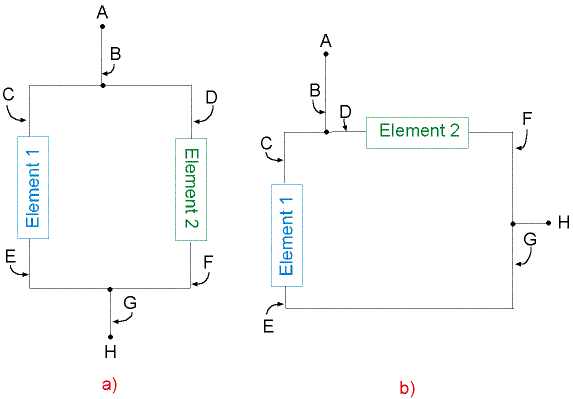
Consider Fig. 13.5 which shows two circuits which look different, but which are actually electrically equivalent.
 |
Figure 13.5
You should have seen from your measurements in lab that the voltage does not change along a length of wire, regardless of whether it’s bent or split (or at least the change is very small). This is because the resistance of the wire is very small. From Ohm’s law, we must have that
where I is the current flowing through the wire. It then follows that, if Rwire is very close to zero, then DVwire will also be very close to zero. When solving problems (unless told otherwise), we will always assume that Rwire = 0, so that DVwire = 0. (This is usually a very good approximation, as we saw in lab.) It therefore follows that, whatever the voltage is at point A in Fig. 13.5, the voltage must be the same at points B, C, and D (since we’ve only moved along wire to go to any of these points).
Likewise, let’s say that the voltage at point H has some value that we shall denote VH. Then the voltage at points G, E, and F must also be VH. This means that the voltage difference across circuit element 1 and circuit element 2 must be the same:
the voltage between the two ends of the elements. This demonstrates the first characteristic of circuit elements in parallel:
Circuit elements in parallel have the same voltage across them.
The second characteristic of circuit elements connected in parallel is very straightforward to see from Figs. 13.5. Recall from Figs. 13.2 that a node is a place where a wire splits and current has a choice of where to go. Examination of Figs. 13.5 shows us that there are two nodes in the portion of circuit shown: one node at point B and the other at point G. The two ends of both circuit elements in parallel are connected at these two nodes. (You can go from point C to point D or from point E to point F by following just wire.) This demonstrates the second characteristic of circuit elements in parallel:
Circuit elements in parallel are connected between the same two nodes in a circuit.
Power Sources in Parallel
It is not uncommon to connect a number of batteries which have the same voltage in parallel with one another. Remember that circuit elements connected in parallel are connected between the same two nodes in a circuit. This means that all of the batteries serve to keep the voltage difference between the two common nodes at the same value. So what purpose would this serve? Simply that batteries represent a finite energy supply (relative to other power sources which can have an external energy source, such as the wall outlet in your lab). If you need 10 V in a circuit and you hook up one 10-V battery, then depending on how much current is demanded by the circuit, the battery may “go dead” after a relatively short period of time. Increasing the number of 10-V batteries connected in parallel will serve to keep the potential difference at 10 V, as before, but now the circuit will “run” for a longer period of time since there is a greater energy reservoir in the combination of batteries. It is otherwise very bad practice to connect two power sources in parallel (they just end up fighting one another), so we will not address this type of connection further.
Resistors in Parallel
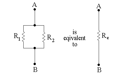
For two resistors connected in parallel, the equivalent resistance can be obtained by solving for Re in the following equation:
 |
Figure 13.6
The same rule above still applies if more than two resistors are connected in parallel. For example, the rule for three resistors is: