When light of wavelength l is sent through a circular hole that has been cut in the middle of a thin board and is subsequently incident on a distant viewing screen, it is found that the light interferes on the screen to form a circular diffraction pattern. In particular, there is found to be a central, circular bright spot (a diffraction maximum) surrounded by a series of concentric rings of alternating dark and bright regions.
More specifically, consider a small circular aperture having a diameter d that is a distance L from a viewing screen. The light is of wavelength l, and the radius of the circular pattern viewed on the screen is denoted r. See Fig. 5.1 below.
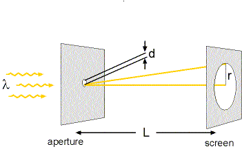 |
Figure 5.1
The circular bulls-eye pattern viewed on the screen was first explained mathematically by Sir George Biddell Airy in 1835. The central bright region of the diffraction pattern observed on the screen is called the Airy disk in his honor. (See Fig. 5.2 below.) The Airy disk has a size determined by the radius of the first dark (destructive interference) ring surrounding it. This radius, denoted r1, is given by
where n is the index of refraction of the medium between the circular aperture and the screen, and ln = l/n is the wavelength of the light within that medium. (For example, if the aperture is the pupil in your eye and the screen is the retina, then you should use n = 1.36, the average index of refraction of the inside of your eye.)
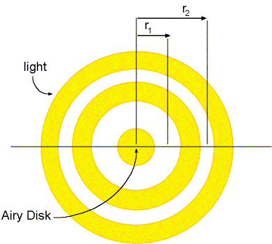 |
Figure 5.2
Moving out from the center of the observed diffraction pattern, there is then a bright circular ring surrounded by a second dark ring of radius denoted r2, given by
Lets imagine that an x-axis is drawn on the screen through the center of the circular diffraction pattern shown in Fig. 5.2 above. If we were to plot the brightness, or intensity, I, of the light pattern as a function of the position x along the screen, then we would get a plot similar to that shown in Fig. 5.3. This figure shows us clearly that a small circular hole with light shining through it does not just project a small circle of light onto a distant screen, but rather a circular bright core (the central bump in the plot of Fig. 5.3) with a kind of ripple of light rings to its sides. (Just imagine the pattern in Fig. 5.3 rotated around the I-axis to understand the two-dimensional light pattern on the screen.)
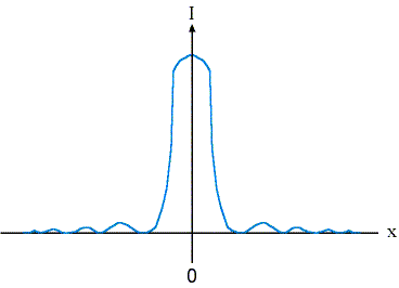 |
Figure 5.3